Contents:
- Arduino IDE Installation
- Arduino IDE and ESP8266 with NodeMCU
- Blinking LED with Arduino
- DHT11(Temperature and Humidity Sensor)
- MQTT
- Using MQTT Protocol and Adafruit Broker to publish DHT11 Data.
Arduino IDE Installation:
Arduino IDE is an Integrated Development Environment where all the required process (libraries, Compiling, Loading code to the device) can be completed on a code. Arduino IDE helps in installing external libraries which are very essential in writing the code for external devices connected to the Arduino kit.
To install Arduino IDE, download the latest version of Arduino IDE from Latest Arduino Download .
After the Download is complete, unzip the installer and install the Arduino IDE with the Default settings.
After the Installation is completed, an Arduino IDE window opens which is shown in figure 1.
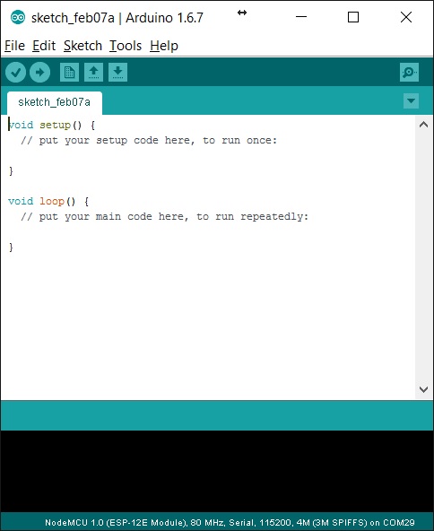
Figure 1: Arduino IDE
To program the Arduino Kits, the basic installation is sufficient. But in order to connect external peripheral devices to the Arduino and make them work, we need to install external libraries.
To install the libraries, first we need to download the required library.

Figure 2: Installing the Libraries
The detailed description on the libraries and their usage is provided in the LED and Sensors projects section.
Arduino IDE and ESP8266 with NodeMCU:
NodeMCU is a board on which the ESP8266 is mounted in order to connect it to the External devices or to form circuits.
The NodeMCU has many pins like GPIO and SPI for connecting to the external devices. The NodeMCU kit and the PIN Diagram is shown in Figure3.
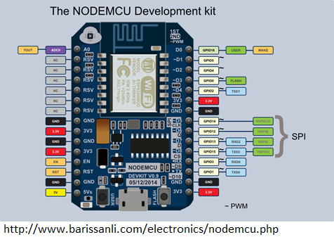
Figure 3: NodeMCU Development Kit
To configure the Arduino IDE to code the ESP8266, we need to install the ESP8266 Arduino Add-on. To do this we need to follow the below mentioned steps.
- Update the Board Manager with the custom URL that is present in the preferences.
Path: File->Preferences->Additional Board Managers URL.
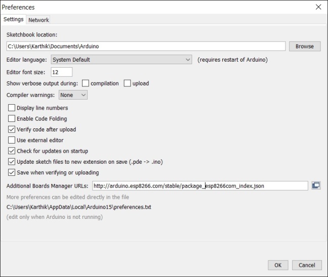
Figure 4: Location for Additional Board Manager Preference
Click OK to set the preference with the new URL and Exit the window.
2. With the Preference set with the new URL, ESP8266 Board definitions and Tools can be installed on the Arduino IDE. For this we need to Tools> Boards > Boards Manager.
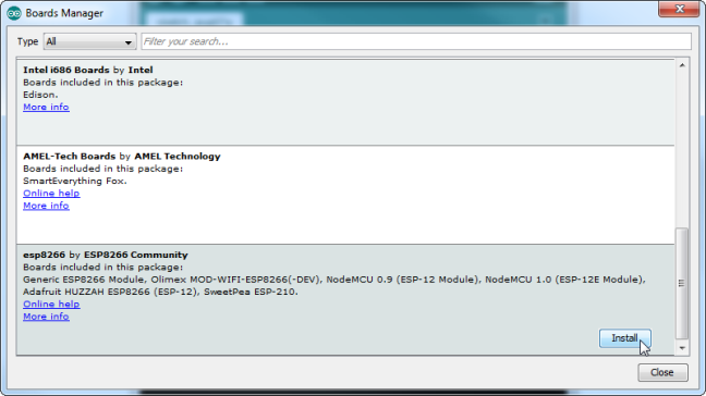
Figure 5: Boards Manager to install the ESP8266.
Click on Install to install the ESP8266 board on the Arduino IDE
3. After the installation is complete, we need to update the IDE with the board with the ESP8266 model. For this we need to select the “NodeMCU-ESP12E” in the Tools->Boards menu option as shown in Figure 6.

Figure 6: Setting Board Configurations to NodeMCU ESP-12E
4. The IDE is now enabled to program the ESP8266. Once the code is written we can dump the code to the Arduino Kit using the IDE and the Kit connected to the Laptop using the USB cable.
5. Before dumping the code, we need to select the port to which the kit is connected. For this follow the path: Tools->Port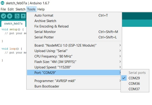
Figure 7: Path to select the Port
Blinking LED with Arduino:
Blinking LED is a basic operation that can be coded on to the Arduino with ease. In order to make the LED blink on the Arduino, we need to connect the LED to the NodeMCU board mounted on the Breadboard.
LED Blinking Code:
#define ESP8266_LED 4
void setup()
{
pinMode(ESP8266_LED, OUTPUT);
}
void loop()
{
digitalWrite(ESP8266_LED, HIGH);
delay(5000);
digitalWrite(ESP8266_LED, LOW);
delay(5000);
}
After the code is written on the IDE, we need to build the code and if no errors were found, we can connect the kit to the port, select the port number on the IDE and click on UPLOAD option to upload the code to the ESP8266. After the uploading is completed, the Led on the device starts blinking based on the time set in the code.
DHT11(Temperature and Humidity Sensor):
DHT11 sensor requires additional libraries for it to be programmed and give results. For this we can download the libraries for the DHT11 and install the libraries in the Arduino IDE as shown in Figure 2.
Once the Libraries are installed, we can use the example codes that are provided in the library or write our own code. Let us look at where to find the example code in the IDE.
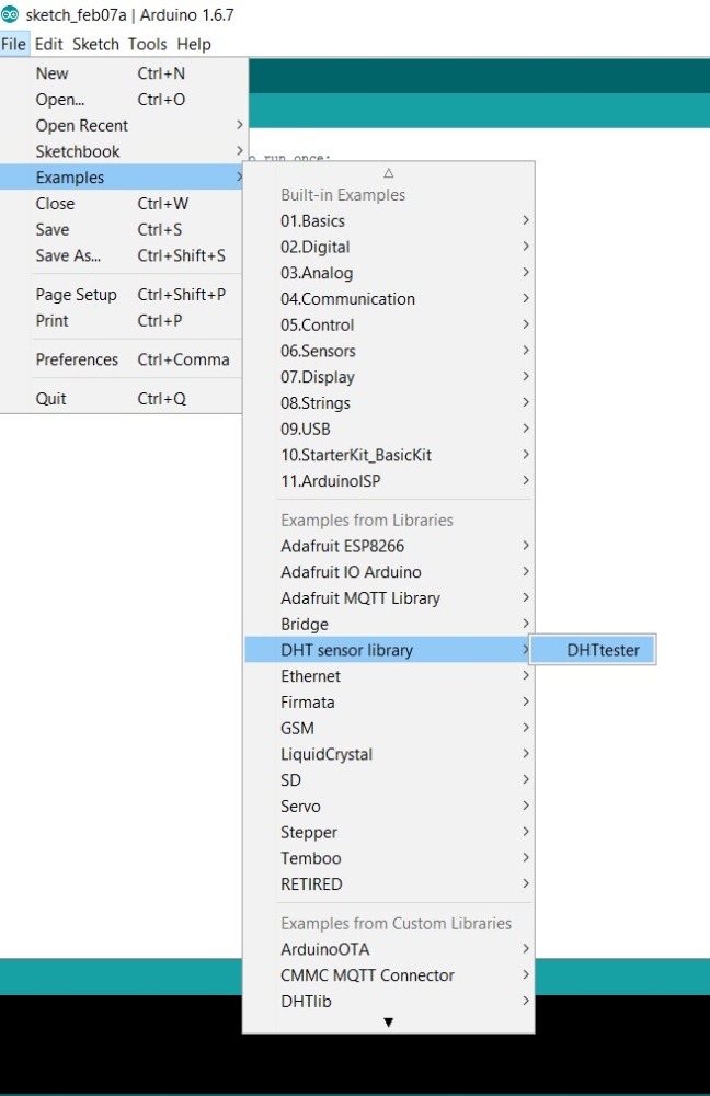
Figure 8: Path to find the example code after the installation of the Library.
The circuit for connecting the DHT11 on the NodeMCU can be validated from the example code.
The DHT sensor has 4 pins.
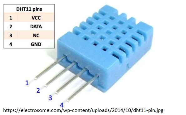
Figure 9: DHT11 pin Diagram.
ESP8266 can be powered by the USB that is used to connect it to the system to upload the code. So no external source of power is required for the device to work or to perform any operation.
To connect the DHT to the ESP8266 or the NodeMCU, we need to mount both the devices on the Breadboard.
Pin 1 of DHT11 is the VCC or the power input and it can be connected to any 3.3v output pin on the NodeMCU.
Pin 2 is the Data pin and it should be connected to the D4 pin as is mentioned in the code.
Pin 4 is the ground pin and can be connected to any GND pin on the NodeMCU
Pin 3 need not be connected.
The Pin Diagram of NodeMCU is provided in Figure 3.
The Circuit after the connection of the pins looks like the one shown in Figure 10.
In order to make the circuit completely functional we need to upload the code to the kit which can again be found in the examples of the DHT11 library.
Open the code, compile it and upload the code to the kit to see the results.
Some modifications should be made to the code as the code provided in the examples can be used for DHT series of sensors.
We need to comment or remove comments to enable DHT11 in the code.
The code that can be used to upload is also provided in the next section.

Figure 10: DHT11 connected to NodeMCU.
DHT11 Code:
// Example testing sketch for various DHT humidity/temperature sensors
// Written by ladyada, public domain
#include “DHT.h”
#define DHTPIN 2 // what digital pin we’re connected to
// Uncomment whatever type you’re using!
#define DHTTYPE DHT11 // DHT 11
//#define DHTTYPE DHT22 // DHT 22 (AM2302), AM2321
//#define DHTTYPE DHT21 // DHT 21 (AM2301)
// Connect pin 1 (on the left) of the sensor to +5V
// NOTE: If using a board with 3.3V logic like an Arduino Due connect pin 1
// to 3.3V instead of 5V!
// Connect pin 2 of the sensor to whatever your DHTPIN is
// Connect pin 4 (on the right) of the sensor to GROUND
// Connect a 10K resistor from pin 2 (data) to pin 1 (power) of the sensor
// Initialize DHT sensor.
// Note that older versions of this library took an optional third parameter to
// tweak the timings for faster processors. This parameter is no longer needed
// as the current DHT reading algorithm adjusts itself to work on faster procs.
DHT dht(DHTPIN, DHTTYPE);
void setup() {
Serial.begin(9600);
Serial.println(“DHTxx test!”);
dht.begin();
}
void loop() {
// Wait a few seconds between measurements.
delay(10000);
// Reading temperature or humidity takes about 250 milliseconds!
// Sensor readings may also be up to 2 seconds ‘old’ (its a very slow sensor)
float h = dht.readHumidity();
// Read temperature as Celsius (the default)
float t = dht.readTemperature();
// Read temperature as Fahrenheit (isFahrenheit = true)
float f = dht.readTemperature(true);
// Check if any reads failed and exit early (to try again).
if (isnan(h) || isnan(t) || isnan(f)) {
Serial.println(“Failed to read from DHT sensor!”);
return;
}
// Compute heat index in Fahrenheit (the default)
float hif = dht.computeHeatIndex(f, h);
// Compute heat index in Celsius (isFahreheit = false)
float hic = dht.computeHeatIndex(t, h, false);
Serial.print(“Humidity: “);
Serial.print(h);
Serial.print(” %\t”);
Serial.print(“Temperature: “);
Serial.print(t);
Serial.print(” *C “);
Serial.print(f);
Serial.print(” *F\t”);
Serial.print(“Heat index: “);
Serial.print(hic);
Serial.print(” *C “);
Serial.print(hif);
Serial.println(” *F”);
}
After the code is uploaded in to the Kit, the code starts to work and the Humidity and temperature values are printed.
To view the output on screen we can open the Serial Monitor from Tools->Serial Monitor
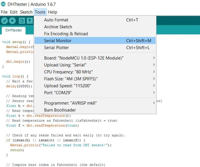
Figure 11: Location to open Serial Monitor to view the output.
The results for the DHT11 sensor can be seen in the Serial Monitor window as shown in Figure 12.
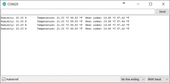
Figure 12: Output from the DHT11 sensor being displayed on the Serial Monitor.
The purpose of IOT to provide this result to the centralized system where the data can be analyzed or the data can be sent to other devices which uses the data to do some other task. For this we are going to use a special protocol called MQTT protocol.
MQTT:
MQTT abbreviated as Message-Queuing-Telemetry-Transport is a light weight protocol that can be used to as a means of communication between multiple devices.
The communication requires data to be published and subscribed by the devices to provide the data or to use the data respectively.
There are many protocols that can be used for the communication of devices like the HTTP, REST, SOAP and many more.
Advantages of MQTT Protocol:
- As already mentioned MQTT is a light weight protocol that works by publish/subscribe method. This is a light weight protocol which implies that the power consumption is very less when compared to other protocols and so IOT devices can be made more power efficient.
- Unlike HTTP which is a request-response system and used for large transport of data, MQTT is always open in communication between the devices and the data transfer between the devices is less.
- The communication between the devices is always open which is not in the case of HTTP where the connection closes once the response is given.
- Latency of communication and data transfer is very low in MQTT when compared to HTTP and other protocols.
- The reliability of the data transfer in the first attempt is high for MQTT.
Considering all the above reasons we are going to use MQTT protocol to publish the data from the DHT11 sensor to view the temperature and humidity values on some device far away from the sensor.
MQTT Broker:
To use the MQTT service we need to register to any one of the MQTT Brokers. MQTT Broker is a system that acts as a centralized hub for all the devices that are publishing data and the devices that wants to subscribe to the data.

Figure 13: MQTT Broker and the devices connected to the broker to publish and subscribe data.
There are many MQTT brokers like Hive, Mosquito and many more. I am going to use Adafruit’s MQTT Broker.
Adafruit MQTT Broker:
To use the Adafruit MQTT Broker, we need to first register to the io.adafruit.com. Once registered, we can generate the credentials required to connect the devices to the Broker.
Figure 14 shows the options available on the MQTT broker once the user creates an account on the io.adafruit.com.
The menu contains many options of which we will be looking into Dashboard and Feeds.
Dashboard is the place where we can place all the feeds that are created in one place that are related to a particular project. There are many interfaces that can be placed on the dashboard once a dashboard and feeds are created.
Feed is a place where we can create new feeds that are used to display the data from the IOT devices. The data in the feeds can be either published or subscribed as per the requirement.
The code that is required and the libraries that are to be installed in order to publish and subscribe the data is explained in the next section.
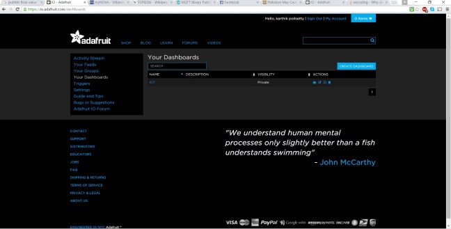
Figure 14: io.Adafruit MQTT Broker menu.
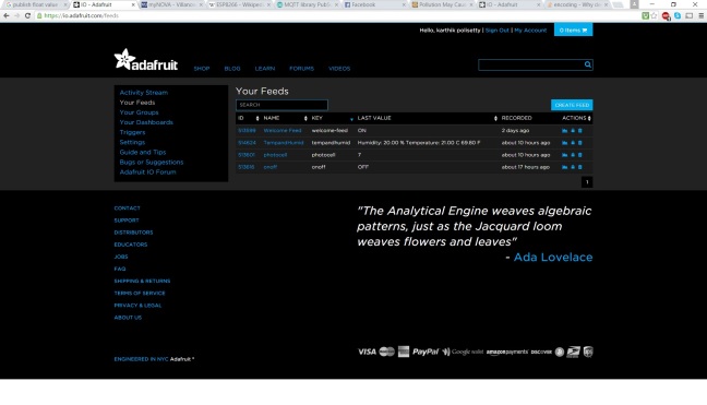
Figure 15: Creating a feed in the Adafruit Broker.
Once the Dashboard and Feeds are created. Click on the created Dashboard to open and to create the blocks that are used to display various types of data that can be received from an IOT Device.
The blocks that we are going to use here are the photocell(Gauge), onoff switch (Toggle Button) and Stream Block (to display temperature and humidity values).
Figure 16 shows the blocks that are created on the dashboard to use for the project.
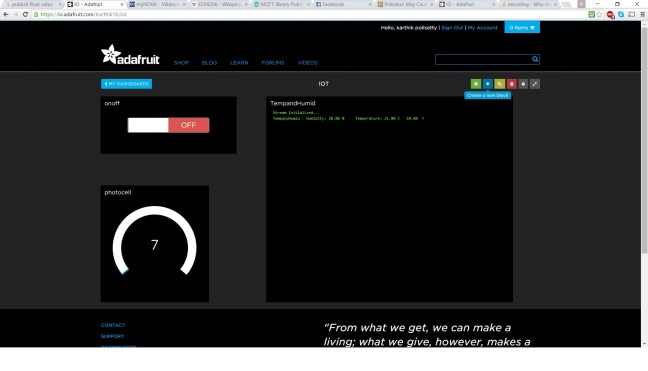
Figure 16: Blocks created on the Dashboard.
Installing the Library for MQTT on Arduino:
The Libraries for the adafruit MQTT can be downloaded from the github at the URL provided. https://github.com/adafruit/Adafruit_MQTT_Library . If we are already registered on the Github then we can directly clone the entire libraries folder into the local computer.
Once the library is downloaded, install the libraries on the Adafruit Ide as explained in the previous sections. Once the libraries are installed, go to File->Examples->Adafruit MQTT Library -> mqtt_esp8266.
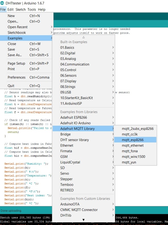
Figure 17: Example code for mqtt_esp8266 to connect to MQTT broker.
The code that is required to publish the Temperature and humidity data, publish the number of times the values are published and the process to subscribe to the device using the swith on to the MQTT Broker is provided below.
Code:
This code is different from the code that is present in the mqtt_esp8266. An extra piece of code is added to publish the temperature and humidity values and the libraries of DHT11 are included and the operations to retrieve the data from the DHT11 is added to the code.
To connect to the MQTT Broker, we need the Adafruit username, key and the WIFI credentials to which the IOT device can connect.
The feed names that are provided in the code can be changed as per the user choice as given on the io.adafruit.com/feeds.
To get the Key.
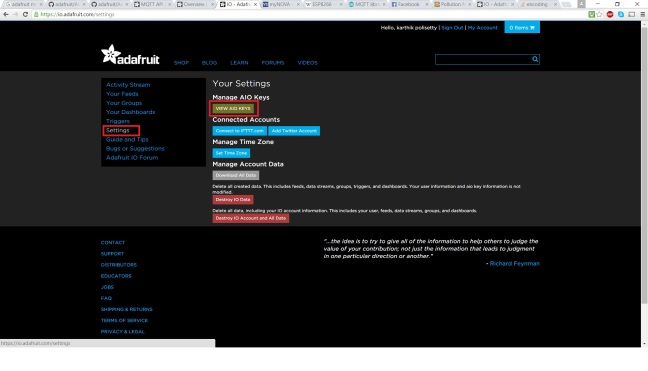 Figure 18: Getting the Adafruit key for MQTT
/***************************************************
Adafruit MQTT Library ESP8266 Example
Must use ESP8266 Arduino from:
https://github.com/esp8266/Arduino
Works great with Adafruit’s Huzzah ESP board & Feather
—-> https://www.adafruit.com/product/2471
—-> https://www.adafruit.com/products/2821
Adafruit invests time and resources providing this open source code,
please support Adafruit and open-source hardware by purchasing
products from Adafruit!
Written by Tony DiCola for Adafruit Industries.
MIT license, all text above must be included in any redistribution
****************************************************/
#include <ESP8266WiFi.h>
#include “Adafruit_MQTT.h”
#include “Adafruit_MQTT_Client.h”
#include “DHT.h”
/************************* DHT Type And Data Pin *****************************/
#define DHTPIN 2
#define DHTTYPE DHT11
/************************* WiFi Access Point *********************************/
#define WLAN_SSID “xxxxxxxxxxxxxx” \\Replace “x” with the value
#define WLAN_PASS “xxxxxxxxxxxxxx”
/************************* Adafruit.io Setup *********************************/
#define AIO_SERVER “io.adafruit.com”
#define AIO_SERVERPORT 1883 // use 8883 for SSL
#define AIO_USERNAME “xxxxxxxxx”
#define AIO_KEY “xxxxxxxxxxxxxxxxxxxxxxxxx”
/************ Global State (you don’t need to change this!) ******************/
// Create an ESP8266 WiFiClient class to connect to the MQTT server.
WiFiClient client;
// or… use WiFiFlientSecure for SSL
//WiFiClientSecure client;
// Store the MQTT server, username, and password in flash memory.
// This is required for using the Adafruit MQTT library.
const char MQTT_SERVER[] PROGMEM = AIO_SERVER;
const char MQTT_USERNAME[] PROGMEM = AIO_USERNAME;
const char MQTT_PASSWORD[] PROGMEM = AIO_KEY;
// Setup the MQTT client class by passing in the WiFi client and MQTT server and login details.
Adafruit_MQTT_Client mqtt(&client, MQTT_SERVER, AIO_SERVERPORT, MQTT_USERNAME, MQTT_PASSWORD);
/****************************** Feeds ***************************************/
// Setup a feed called ‘photocell’ for publishing.
// Notice MQTT paths for AIO follow the form: <username>/feeds/<feedname>
const char PHOTOCELL_FEED[] PROGMEM = AIO_USERNAME “/feeds/photocell”;
Adafruit_MQTT_Publish photocell = Adafruit_MQTT_Publish(&mqtt, PHOTOCELL_FEED);
const char TEMPANDHUMID_FEED[] PROGMEM = AIO_USERNAME “/feeds/TempandHumid”;
Adafruit_MQTT_Publish TempandHumid = Adafruit_MQTT_Publish(&mqtt, TEMPANDHUMID_FEED);
// Setup a feed called ‘onoff’ for subscribing to changes.
const char ONOFF_FEED[] PROGMEM = AIO_USERNAME “/feeds/onoff”;
Adafruit_MQTT_Subscribe onoff = Adafruit_MQTT_Subscribe(&mqtt, ONOFF_FEED);
/*************************** Sketch Code ************************************/
// Bug workaround for Arduino 1.6.6, it seems to need a function declaration
// for some reason (only affects ESP8266, likely an arduino-builder bug).
void MQTT_connect();
DHT dht(DHTPIN, DHTTYPE);
void setup() {
Serial.begin(115200);
delay(10);
Serial.println(“DHT11 test!”);
Serial.println(F(“Adafruit MQTT demo”));
// Connect to WiFi access point.
Serial.println(); Serial.println();
Serial.print(“Connecting to “);
Serial.println(WLAN_SSID);
WiFi.begin(WLAN_SSID, WLAN_PASS);
while (WiFi.status() != WL_CONNECTED) {
delay(500);
Serial.print(“.”);
}
Serial.println();
Serial.println(“WiFi connected”);
Serial.println(“IP address: “); Serial.println(WiFi.localIP());
dht.begin();
// Setup MQTT subscription for onoff feed.
mqtt.subscribe(&onoff);
}
uint32_t x=0;
void loop() {
// Ensure the connection to the MQTT server is alive (this will make the first
// connection and automatically reconnect when disconnected). See the MQTT_connect
// function definition further below.
MQTT_connect();
// this is our ‘wait for incoming subscription packets’ busy subloop
// try to spend your time here
Adafruit_MQTT_Subscribe *subscription;
while ((subscription = mqtt.readSubscription(10000))) {
if (subscription == &onoff) {
Serial.print(F(“Got: “));
Serial.println((char *)onoff.lastread);
}
}
// Sensor readings may also be up to 2 seconds ‘old’ (its a very slow sensor)
float h = dht.readHumidity();
// Read temperature as Celsius (the default)
float t = dht.readTemperature();
// Read temperature as Fahrenheit (isFahrenheit = true)
float f = dht.readTemperature(true);
// Check if any reads failed and exit early (to try again).
if (isnan(h) || isnan(t) || isnan(f)) {
Serial.println(“Failed to read from DHT sensor!”);
return;
}
// Now we can publish stuff!
Serial.print(F(“\nSending photocell val “));
Serial.print(x);
Serial.print(“…”);
if (! photocell.publish(x++)) {
Serial.println(F(“Failed”));
} else {
Serial.println(F(“OK!”));
}
char message_buff[160];
// Compute heat index in Fahrenheit (the default)
float hif = dht.computeHeatIndex(f, h);
// Compute heat index in Celsius (isFahreheit = false)
float hic = dht.computeHeatIndex(t, h, false);
Serial.print(F(“Humidity: “));
Serial.print(h);
Serial.print(F(” %\t”));
Serial.print(F(“Temperature: “));
Serial.print(t);
Serial.print(F(” *C “));
Serial.print(f);
Serial.print(F(” *F\t”));
String humid = String(h);
String TempC = String(t);
String TempF = String(f);
String pub = “Humidity: ” + humid+ ” %”+” Temperature: “+ TempC + ” C “+TempF+” F”;
pub.toCharArray(message_buff, pub.length()+1);
if (! TempandHumid.publish(message_buff)) {
Serial.println(F(“Failed”));
} else {
Serial.println(F(“OK!”));
}
// ping the server to keep the mqtt connection alive
// NOT required if you are publishing once every KEEPALIVE seconds
/*
if(! mqtt.ping()) {
mqtt.disconnect();
}
*/
}
// Function to connect and reconnect as necessary to the MQTT server.
// Should be called in the loop function and it will take care if connecting.
void MQTT_connect() {
int8_t ret;
// Stop if already connected.
if (mqtt.connected()) {
return;
}
Serial.print(“Connecting to MQTT… “);
uint8_t retries = 3;
while ((ret = mqtt.connect()) != 0) { // connect will return 0 for connected
Serial.println(mqtt.connectErrorString(ret));
Serial.println(“Retrying MQTT connection in 5 seconds…”);
mqtt.disconnect();
delay(5000); // wait 5 seconds
retries–;
if (retries == 0) {
// basically die and wait for WDT to reset me
while (1);
}
}
Serial.println(“MQTT Connected!”);
}
Once the code is modified as per the user credentials, the code need to be built to verify any compilation errors. If no Error found, then connect the NodeMCU which is mounted on the breadboard and the humidity sensor is connected to the pins.
Upload the code to the device.
Once the code is uploaded, the device starts working as per the code and the result can be seen on IDE on the Serial Monitor window.
We can see the data being published on the io.Adafruit.com/dashboards website once the user logs in.
The humidity and temperature values are displayed in the Stream Block; the number of times the values are published is published in the Gauge Block; the subscription can be shown using the toggle button. Where the position of the switch is displayed on the serial monitor once the switch operation is performed on the switch on the dashboard.
The Results for the same can be shown in the Figure 19 and Figure 20 respectively.

Figure 19: Results of the sensor (temperature and Humidity values being published) and the corresponding count on the gauge.
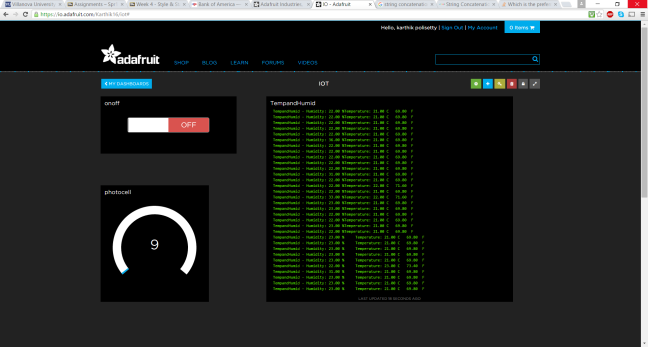
Figure 20: Update code that provided spaces between the values and the corresponding new count on the gauge.
Conclusion: After the completion we will be able to connect more number of devices to the Broker and publish / subscribe the data to and from the devices.

One thought on “Tutorial on Arduino and MQTT”