Connecting the DHT11 sensor to PI
The DHT11 sensor is a device capable of sensing the air humidity and temperature at the most economical way and it is very convenient to use as it has only 4 pins in order.
- VCC – this pin provides the power source to the sensor to enable sensing.
- GND – Whenever any device is connected to the power source, it also needs to be connected to the ground and the ground pin is connected to the ground pin in the circuit.
- DATA – This pin provides the actual results (air temperature and humidity) that are sensed. The data is transferred in bits.
- NC – Not connected. This pin is not connected to the circuit.
Figure 1 provides a clear view of the pins. Remember that the pins are numbered 1 to 4 from left to right when the open side of the sensor is facing you.
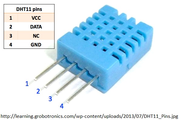
Figure 1: Pin Diagram of the DHT11
Connecting DHT11 to the PI
In order to make the results of the sensor visible, it should be connected to some device which can interpret and display the values. For this purpose, we are using Raspberry Pi to display the values.
The Circuit diagram to connect the DHT11 and Raspberry Pi is given in Figure 2.
The VCC pin of the DHT11 is connected to the 3.3v out pin of the Pi.
The DATA pin is connected to the GPIO (General Purpose Input and output) Pin 4.
Here we need to use either 4.7 kohm or 10 kohm resistor to provide a bride between VCC and DATA pin. The resistance acts as a medium-strength pull up on the DATA.
The GND pin of the DHT11 can be connected to any ground on the PI.
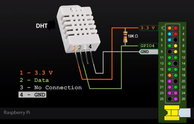
Figure 2: Circuit Diagram to connect DHT11 to PI
Providing the connections and powering it on is not sufficient for DHT11 sensor to work and display the result. This requires some software as well, like the code and the libraries that are to be installed on the system on which the code is to be run.
The codes (C or Python) to work with Adafruit’s DHT sensors is available on GitHub at: https://github.com/adafruit/Adafruit_Python_DHT (http://adafru.it/dCJ).
To get the codes on to the PI from the source, verify whether the PI is connected to the Internet (either by WIFI or the Ethernet)
Once the WIFI or the Ethernet is connected use the following codes on the PI LXTerminal.
git clone https://github.com/adafruit/Adafruit_Python_DHT.git.
This command is to clone the folder that contains the Python codes as examples and some libraries.
cd Adafruit_Python_DHT
Having the codes is not sufficient to make the code run. Code requires libraries to execute. For this we need to install libraries. So we need to get in to the Adafruit_Python_DHT folder where the libraries are present and the following commands helps to install the libraries on the PI.
sudo apt-get update
sudo apt-get install build-essential python-dev python-openssl
sudo python setup.py install (To install the libraries)
Once the Libraries are successfully installed we need to test the Python Libraries. For this the below commands are helpful.
cd examples (To move into the example codes folder)
Now to run the example on a Raspberry Pi with an DHT11 sensor connected to GPIO #4,
execute: sudo ./AdafruitDHT.py 11 4 (As in the circuit diagram the DATA pin is connected to GPIO #4)
Figure 3: DHT11 Temperature and Humidity Values being displayed
Source Code in python:
The Code that is executed i.e., the code present in AdafruitDHT.py is given below.
In the provided code, some of the values must be modified in order to get the precise values.
To get the Values in Centigrade the Same code can be followed without any changes. But, to get the results in Fahrenheit, the statement” # temperature = temperature * 9/5.0 + 32” should be uncommented.
The same code can be modified to change the values at regular intervals of time by adding an infinite for loop or a while loop to it.
The infinite for loop in python can be written as “for i in itertools.count():” and also the library for the same should be imported to the code “import itertools”
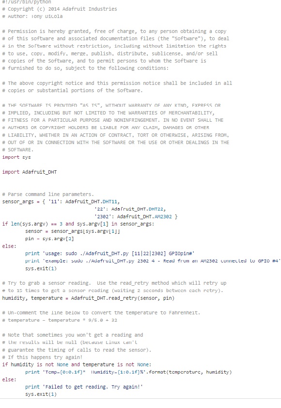
Figure 5: Code to be run to print the temperature and humidity values
RESULTS:
The result that is obtained after the execution of the code before the addition of infinite for loop is as shown below in Figure 6.
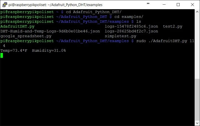
Figure 6: Result after the execution of code
The result after the addition of the for loop to the code and executing it is as shown in Figure 7.
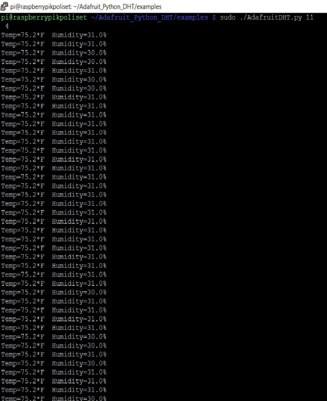
Figure 7: Result after the execution of code with for loop
SPI Interface
SPI abbreviated as Serial Peripheral Interface is an interface bus that is commonly used to transmit and receive data between the electronic devices such as microcontrollers and sensors, memory devices and more. SPI has become so popular as it provides a synchronous communication between the devices. Synchronous communication prevents the loss of data during the transmission as both the devices are in sync with the clock and transmission which does not happen in the case of an Asynchronous communication.
The communication takes place between two devices called Master and a Slave. At any point of time there is only one master and there can be multiple slaves. The Microcontroller however always acts as a master and the devices connected to it, like the sensors, memory devices and other peripherals act as slaves.
The Master is called so because it generates the clock signal that is required for the communication. The controller (Master) communicates to the devices (Slaves) using the line called MOSI (Master Output Slave Input) and if the slave needs to communicate it is done using the MISO line (Master Input Slave Output)
The SPI interface between the Master and Slave can be represented by the figure as given below.
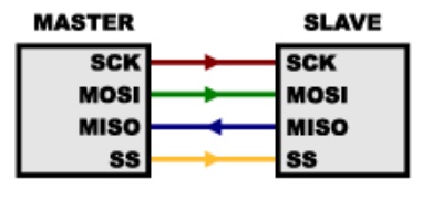
Figure 8: Master and Slave Communication (SPI Interface)
The SS line is the Slave select Line that is used to communicate to a particular Slave when there are multiple slaves connected to the master.
SPI and the Raspberry PI
Raspberry PI is equipped with SPI Interface bus which is disabled by default. First the SPI Master Driver should be enabled in order to use the SPI on the PI which can be done using the following steps.
First Method of Enabling SPI on PI
- Use the LXTerminal shell on the Raspberry PI and use the command sudo raspi-config to open the configuration window.
- In the configuration, click on the Advanced options to open the Advanced options menu which contains the SPI.
- Select the SPI and click on Enable option to enable the SPI on the PI.
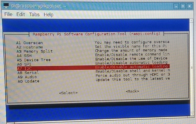
Figure 9: Enabling SPI using raspi-config

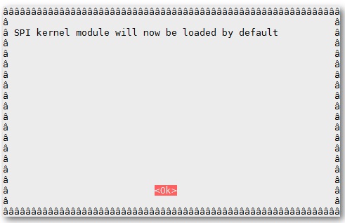
Figure 10: Select Yes to enable the SPI on PI
Once the Enable option is selected with an “Yes”, the PI populates a new window with a message that the SPI will be loaded by default after the reboot.
The SPI can also be disabled using the same process and the effect takes place after the reboot is done on the PI.
Reboot PI for the changes to take effect and the SPI is enabled.
Second Method of Enabling SPI on PI
In this method the SPI is enabled by making some changes in a configuration file using the command line.
The steps for the same are as follows:
- Verify that the PI is up to date using the commands
Sudo apt-get update
Sudo apt-get upgrade
- To make the changes to the system configuration file use the following command to open the file
Sudo nano /boot/config.txt
- In the file add the following line at the bottom
dtparam=spi=on
- Save the file and use Reboot command to reboot
Sudo reboot
Verify whether the SPI is Enabled
To verify whether the SPI is enabled on the PI, open the LXTerminal window and use the following command:
Ismod|grep spi_
Depending on the usage of the pins in master slave communication there are three modes defined called the Master Modes.
Master Modes
There are 3 master modes available on the PI. They are:
- Standard Mode
In standard Master mode, the peripheral implements the 3 wire serial protocol. The three wires are the clock, MOSI and MISO and there are no SS lines.
- Bidirectional Mode
In Bidirectional Master Mode, the only 2 wires are used for communication. Here the communication between master to slave and vice-versa happen only using a single line. As a whole Bidirectional Master Mode = Standard Master Mode with only two lines
- LOSSI Mode
When there is a requirement that the peripherals need to be given some commands, the LOSSI mode is used. It generally uses an 8-bit transmission and an extra bit to determine whether the instruction is a command or data.
Transfer Modes
Depending on how the data is transmitted between the devices there are 3 types of transfer modes. They are:
- Polled Mode:
Polling involves continuous monitoring of the Peripherals to know whether they are connected or whether they want to communicate.
- Interrupted Mode
In this mode the controller issues commands to the peripheral and processes other instructions. When the peripheral or the I/O device completes the task, it sends an interruption to the controller. This mode of transfer is advantages than polling as this saves CPU time and increases efficiency.
- DMA
DMA abbreviated as Direct Memory Access is a special type of mode in which the controller provides the peripheral access to the main memory. This requires CPU operation only during the access grant and this saves a lot of CPU time.
In Raspberry PI only the Interrupt mode is used out of the three modes.

One thought on “DHT11, SPI AND RASPBERRY PI”